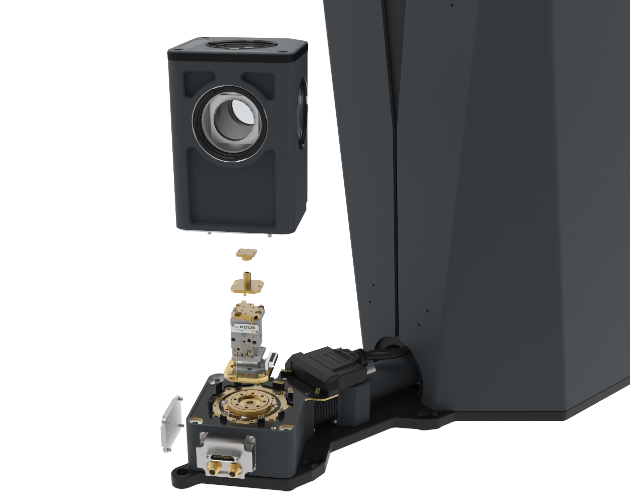
Our Cryostation systems are configurable using standard options chosen from each option category. The physical interface between each category is a design standard so standard options are compatible throughout the CryoAdvance product family. Each option category is listed below, select a category to see the option description, available options within the category, and how that category fits into the overall system design.
Consisting of the taller rear enclosure, thermal cross-link connection, and the lower housing, this is the main body of the Cryostation and contains all the technology for cooling the sample space. The rear enclosure houses the cryocooler and interface panel for the helium compressor and system controller connections. The “lower housing” contains the assemblies that connect the sample chamber platform to the cryocooler cold head and the ports for side panels. The top of this structure is the base of the sample chamber, to which the positioning options attach. Our CryoAdvance product models are differentiated by the internal diameter of the sample chamber: 50mm and 100mm.
Interface between the sample chamber and the environment. Provides outer vacuum housing with ‘warm’ windows and inner radiation shield with ‘cold’ windows. The interior space of the radiation shield is commonly referred to as the “sample chamber”. Configuration options include the standard housing shown here, the Magneto-Optic and CryoOptic products.


These options connect to the platform and are used to manipulate the location of the sample within the chamber. We offer manual positioning options as well as remote-controlled positioning stages.

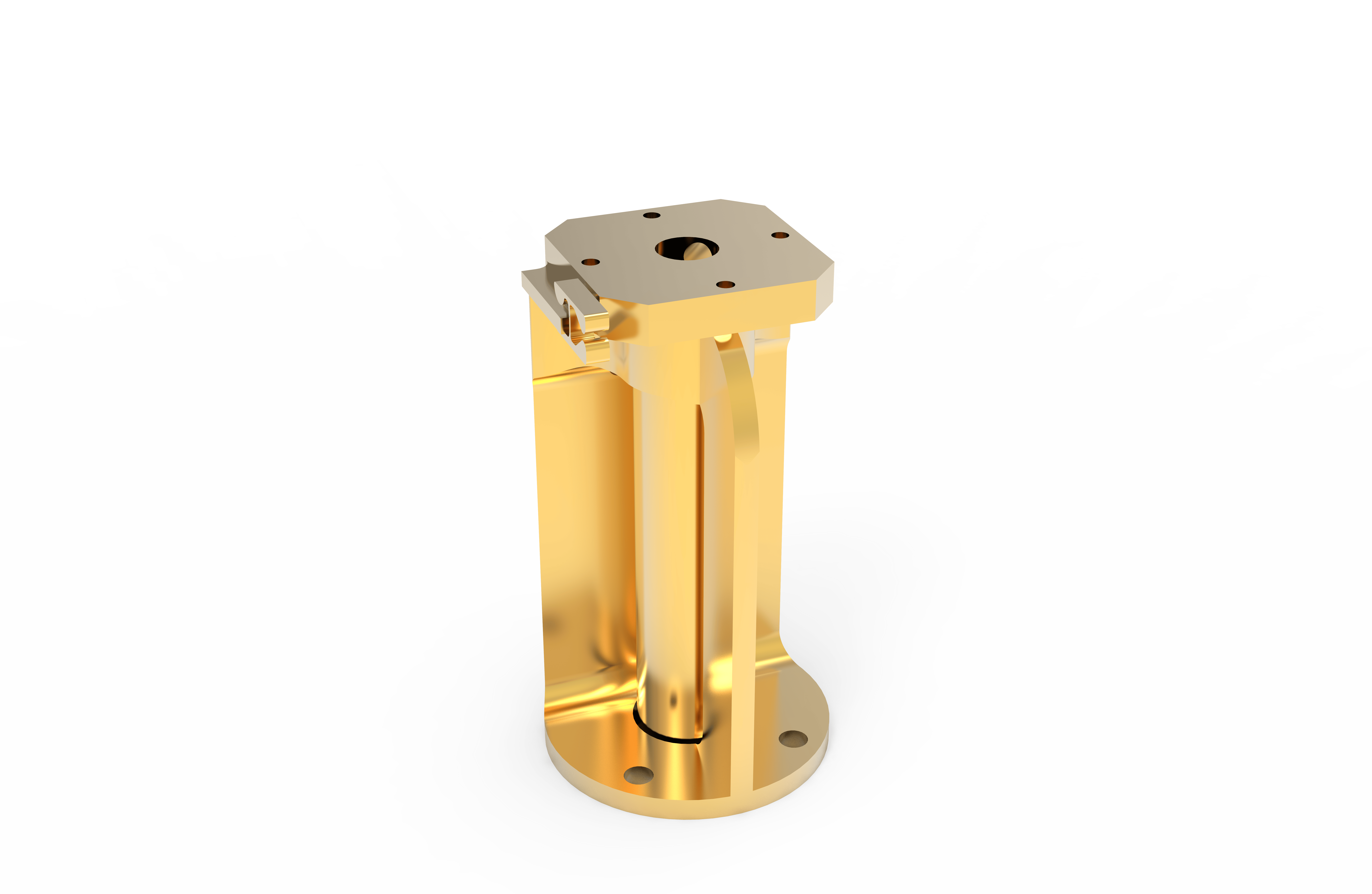
This is the connection between the positioner and the sample mount, utilizing a post that inserts into the sample mount's compression clamp enabling a quick sample mount exchange. All adapter options include a right-angle plate which allows each adapter to orient the sample mount to face either side or top windows. ATSM option provides localized temperature control to the sample.


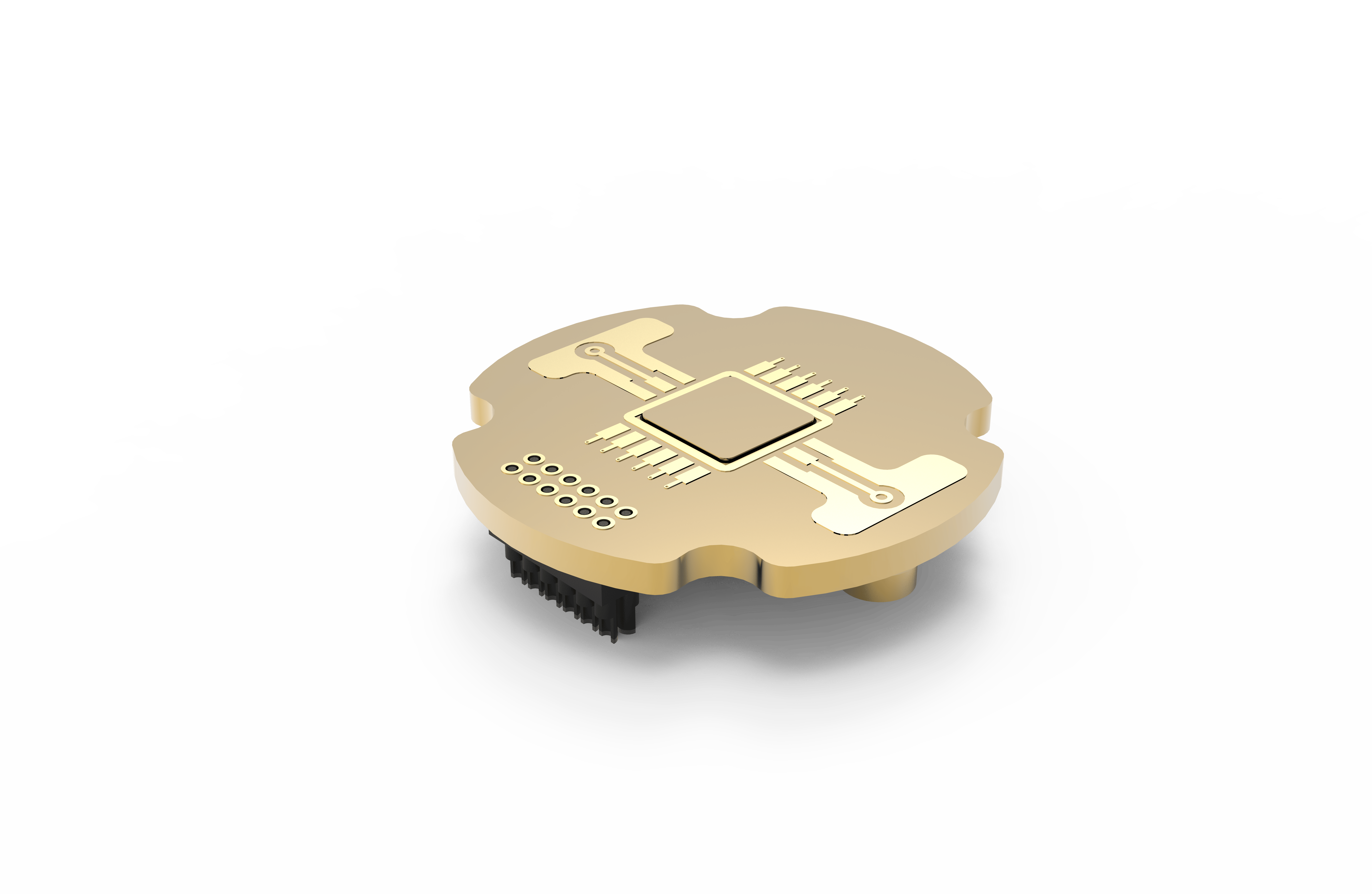
This is where a user attaches the sample material or device. The sample mount connects to the adapter post with a compression fitting, completing the thermal path between cold finger and the sample. Several options utilize a cryogenic-compatible PCB with RF & DC connections for electrical interrogation applications.
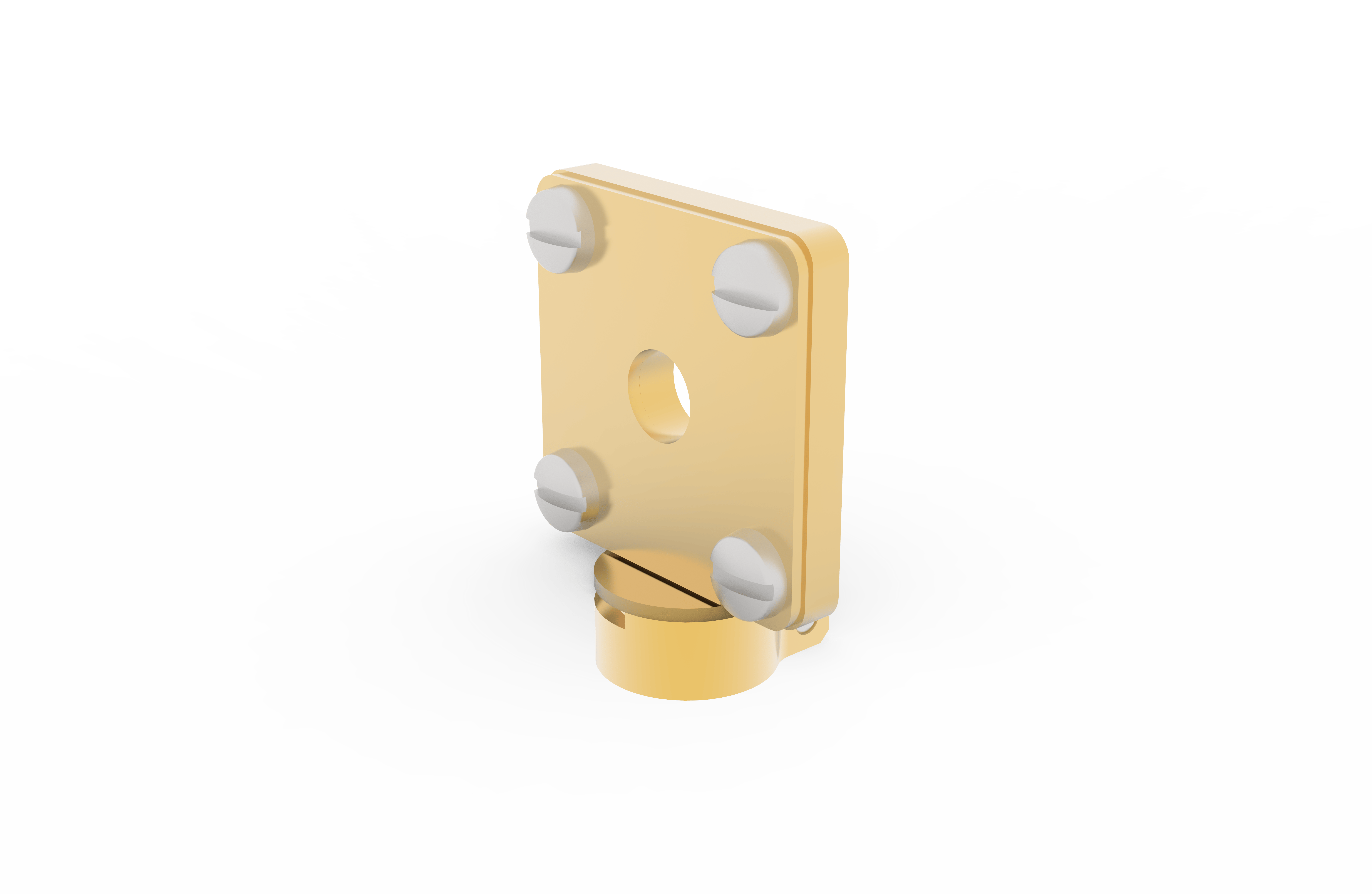

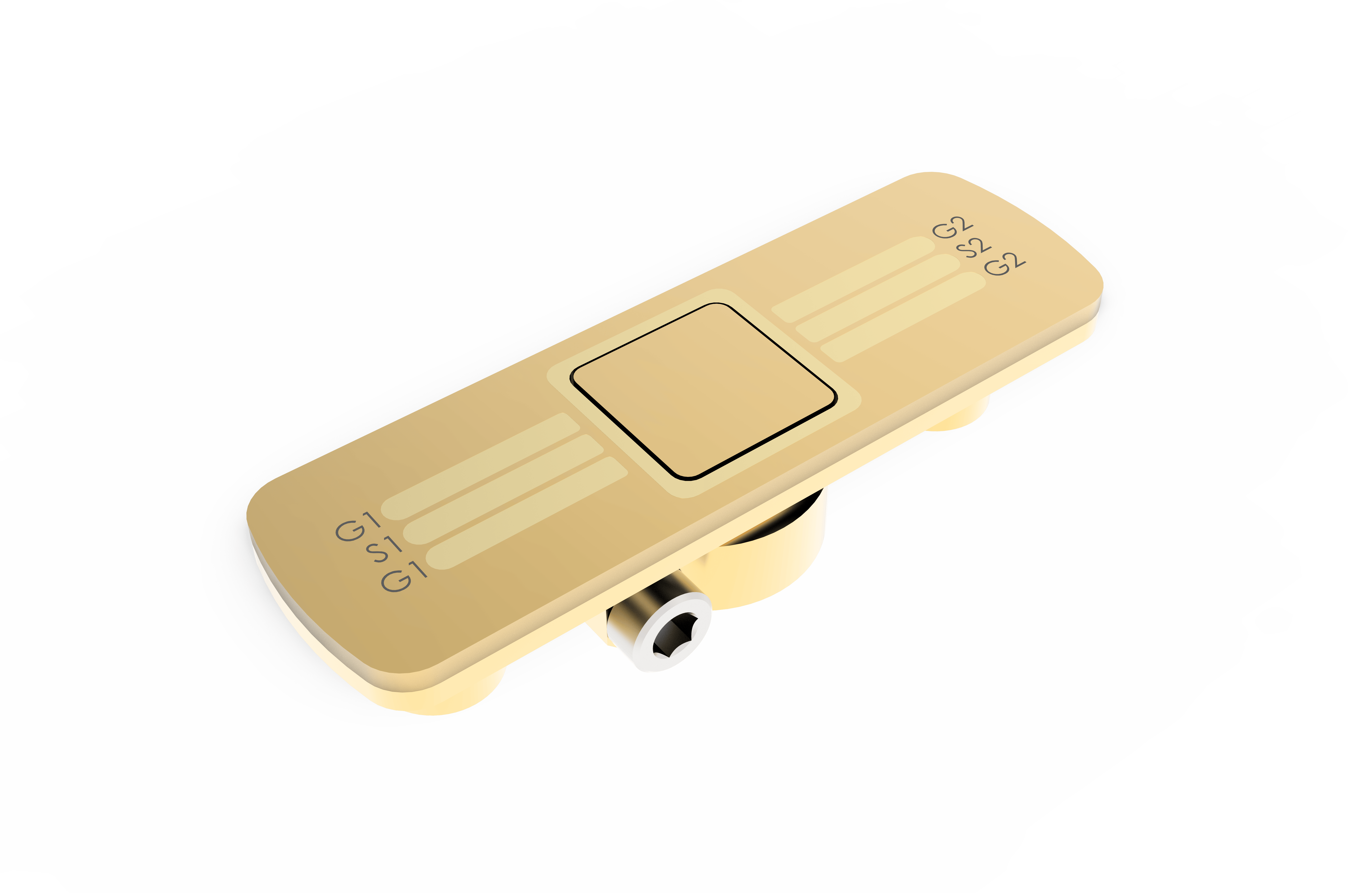
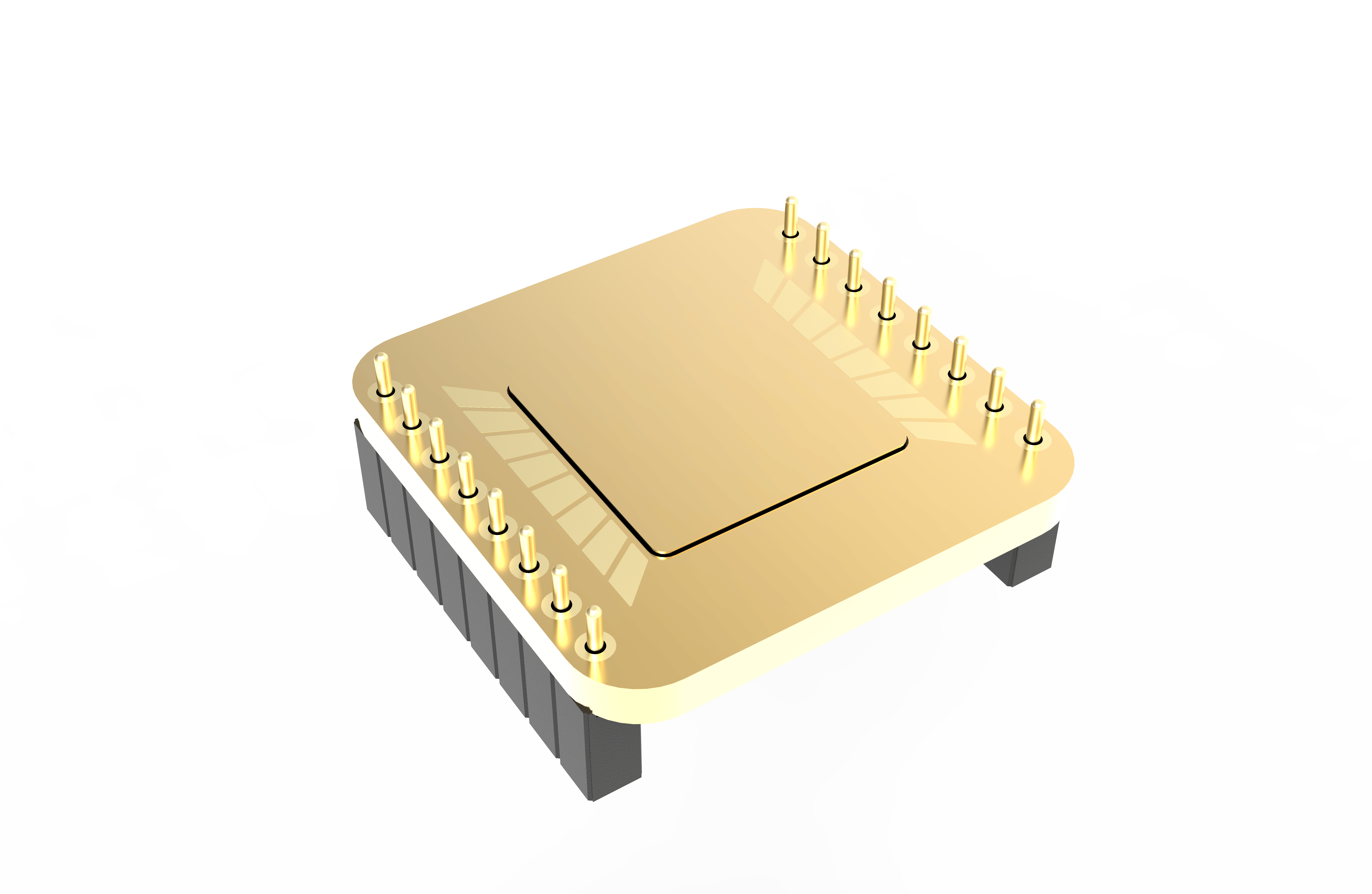
Vacuum-sealed side panels are installed in the lower housing and provide thermally lagged input and output (I/O) connection between the sample chamber and external equipment. Available standard options include RF, DC, and fiber-optic I/O. The CryoAdvance 50 and 100 models have "standard option" RF and DC I/O included with the base system to accommodate most customers’ needs right out of the box. The remaining side panels are configurable typically with choices from our standard options.


These options include the warm and cold windows for housing & radiation shield window ports. Users can choose from several factory-installed window materials in both standard and low working distance options. Window blanks for both 'warm' and 'cold' windows are always shipped with each system's accessory kit.


Consisting of the taller rear enclosure, thermal cross-link connection, and the lower housing, this is the main body of the Cryostation and contains all the technology for cooling the sample space. The rear enclosure houses the cryocooler and interface panel for the helium compressor and system controller connections. The “lower housing” contains the assemblies that connect the sample chamber platform to the cryocooler cold head and the ports for side panels. The top of this structure is the base of the sample chamber, to which the positioning options attach. Our CryoAdvance product models are differentiated by the internal diameter of the sample chamber: 50mm and 100mm.
Interface between the sample chamber and the environment. Provides outer vacuum housing with ‘warm’ windows and inner radiation shield with ‘cold’ windows. The interior space of the radiation shield is commonly referred to as the “sample chamber”. Configuration options include the standard housing shown here, the OneK-Optic and CryoOptic products.


These options connect to the platform and are used to manipulate the location of the sample within the chamber. We offer manual positioning options as well as remote-controlled positioning stages.


This is the connection between the positioner and the sample mount, utilizing a post that inserts into the sample mount's compression clamp enabling a quick sample mount exchange. All adapter options include a right-angle plate which allows each adapter to orient the sample mount to face either side or top windows. ATSM option provides localized temperature control to the sample.


This is where a user attaches the sample material or device. The sample mount connects to the adapter post with a compression fitting, completing the thermal path between cold finger and the sample. Several options utilize a cryogenic-compatible PCB with RF & DC connections for electrical interrogation applications.


Vacuum-sealed side panels are installed in the lower housing and provide thermally lagged input and output (I/O) connection between the sample chamber and external equipment. Available standard options include RF, DC, and fiber-optic I/O. The CryoAdvance 50 and 100 models have "standard option" RF and DC I/O included with the base system to accommodate most customers’ needs right out of the box. The remaining side panels are configurable typically with choices from our standard options.


These options include the warm and cold windows for housing & radiation shield window ports. Users can choose from several factory-installed window materials in both standard and low working distance options. Window blanks for both 'warm' and 'cold' windows are always shipped with each system's accessory kit.


